Wednesday, January 7, 2009

Procedure documentation Configuring Size of Data Packets and Frequency

Use

To upload large sized flat files, the setting of the following parameters within the BW Customizing is important:

  • Size of data packets
  • Frequency

For data transfer into BW, the individual data records are sent in packets of variable size. Using the parameters for the size of data packets you can control how large a data packet typically is. If no entry is maintained, the data is transferred with the default setting of 10,000 Kbytes per data packet. Within BW Customizing you can increase this setting to 40,000 Kbytes or higher.

By specifying the frequency, you determine after how many data IDocs an Info IDoc is sent, or how many data IDocs are described by an Info IDoc. Choose a frequency of between 5 and 10, but not greater than 20.

Procedure

  1. Open the customizing tree from the SAP Easy Access menu under the folder Tools
  2. ® Business Engineer.
  3. Double-click on BW Customizing and select SAP Reference IMG.
  4. Expand the tree BW Customizing Implementation Guide
  5. ® Business Information Warehouse ® Links to Other Systems ® Maintain Control Parameters for the data transfer.
  6. Change the parameters as required.

Expanding Table Spaces

Use

SAP recommends that the following table spaces should be expanded:

  • PSAPSTABD
  • PSAPSTABI
  • PSAPFACTD
  • PSAPFACTI
  • PSAPDIMD
  • PSAPDIMI
  • PSAPCLUD
  • PSAPODSI
  • PSAPTEMP

The following table can be used as a guide. It illustrates the table space sizes that are used to upload 1,8 million records based on an Oracle database.

Table space sizes

Table space

Size (kb)

Free

PSAPSTABD

2.048.000

At least 1.6 GB free

PSAPSTABI

2.048.000

At least 1.6 GB free

PSAPFACTD

716.800


PSAPFACTI

965.904


PSAPDIMD

102.400


PSAPDIMI

117.744

At least 40 MB free

PSAPCLUD

51.200


PSAPODSI

2.702.824


PSAPTEMP

5.013.480

At least 5 GB free

Procedure

For detailed information, see SAP note number 184905.

Customizing BW for the Usage of the D&B Marketing Universe

Procedure

  1. In your BW system, select transaction rsmonitor_db.
  2. From the Environment menu, choose D&B Registration.
  3. Create a new scenario using the Create icon.
  4. If you are using a SAP CRM system, choose the logical system name of your CRM system. If you use a 3rd party CRM leave the logical system blank.
  5. In the field CRM Scenarios choose D&B Integration of external Data.
  6. Save your scenario.

Customizing for Business Partner Creation from BW in SAP CRM

Procedure

  1. In your CRM system, register the InfoObject DUNS Number 0DBDUNS_NUM as an identification object for the business partner.

Use transaction sm30 to maintain the table RSCRMEXTERN as follows:

    • Logical System: system name of the CRM system
    • InfoObject: 0DBDUNS_NUM
    • InfoObject: 0BPARTNER
    • ID Category: BUP001 (provided with the customizing of your CRM system)
    • Maximal allowed age of master data (in calendar days): for example 365 for 1 year
  1. Bear in mind that the D&B scenario is a B2B scenario. Therefore only companies and organizations are considered as business partner. To check if the ID category BUP001 is valid for organizations proceed as follows:
    • In your CRM system, use transaction sm30 to display the table v_tab039A.
    • Mark the row with BUP001 and click on the Details icon.

The Identificationtype should be relevant for organizations only.

InfoPackages for Initial Upload

Together with the first D&B data files you also receive some D&B files containing customer-independent information. These files need to be uploaded only once. To prepare the upload process you create the required InfoPackages.

The following table shows the files you get from D&B for the initial upload. For each file you create one InfoPackage. In the right column you see the InfoObjects to which the new InfoPackages belong.

D&B File

Technical name

InfoObject for which you create the InfoPackage

Legal Status Text File

0DBLGLSTAT_TEXT.CSV

0DBLGLSTAT

D&B Rating Net Worth - Text

0DBRATENW_TEXT_MU.CSV

0DBRATENW

D&B Rating Condition – Text

0DBRATECON_TEXT_MU.CSV

0DBRATECON

D&B Score - Text

0DBSCORE_TEXT_MU.CSV

0DBSCORE

D&B Sector Code - Text

0DBSECTCOD_TEXT_MU.CSV

0DBSECTCOD

Country Code Text File

0DBCTRYCOD_TEXT.CSV

0DBCTRYCOD

D&B Region Code - Text

0DBREGCOD_TEXT_MU.CSV

0DBREGCOD

D&B Area Code - Text

0DBAREACOD_TEXT_MU.CSV

0DBAREACOD

D&B District Code - Text

0DBDISTRCOD_TEXT_MU.CSV

0DBDISTRCOD

SIC Text File

0DB87SIC1_TEXT.CSV

0DB87SIC1

SIC Hierarchy File

0DB87SIC1_HIER.CSV

0DB87SIC1

All the InfoPackages have got the same pattern as described in following table. Create the InfoPackages with this information.

Tab

Field

Value

Select data


No entries required

External data


Load external data from

Application server


File name

A combination of the path of the working directory on the application server and the file name

For example D:\usr\sap\QB5\D19\work/0DBLGLSTAT_TEXT.CSV for InfoPackage 0DBLGLSTAT_TEXT

Ask your system administrator which directories the files will be stored in (see also Storing D&B Data on an Application Server)


Control file

No


File type

CSV file


Data separator

,


Escape sign

"

External data parameters


Thousand separator

,


Character for decimal point


.


Number of headers that should be ignored when loading


1

Processing


Update data

PSA and then in the InfoObject

Update parameters


Update mode

Full update

InfoPackages for Repeated Upload

Each time D&B provides new data, the master data for the InfoObjects DUNS Number (0DBDUNS_NUM) and Customer number (0CUSTOMER) require updating. If you are using a SAP CRM system, the InfoObject Business Partner (0BPARTNER) also requires updating. The data has also to be loaded into the MarketingCube. For this purpose the following files are sent from D&B:


  • D&B Marketing Universe Matched Client File (0DB_IMPORTFILE_MU.csv)

  • D-U-N-S Text File (0DBDUNS_NUM_TEXT_MU.csv)

  • D&B Universe of Abstract Data (0DBDUNS_NUM_ABSTRACT_MU.csv)

The first time you get data from D&B, D&B provides these files in addition to the files required for initial upload.

For the InfoObjects 0CUSTOMER, 0BPARTNER and 0DBDUNS_NUM new InfoPackages are required. The D&B Marketing Cube (InfoSource 0DB_MKT_1) needs one new InfoPackage as well.

  • For the InfoObject 0DBDUNS_NUM you create four InfoPackages for the different data sources:
    • One for the text description (data source 0DBDUNS_NUM_TEXT)
    • Three for the master data upload (for each data source 0DBDUNS_NUM_ATTR, 0DBDUNS_NUM2_ATTR, 0DBDUNS_NUM3_ATTR).
  • For each of the InfoObjects 0CUSTOMER and 0BPARTNER and for the D&B Marketing Cube (InfoSource 0DB_MKT_1) you create one new InfoPackage.

The parameters of the InfoPackages are described in the following tables. Create the InfoPackages with this information.

InfoPackages 0DBDUNS_NUM_TEXT, 0DBDUNS_NUM_ATTR and 0DBDUNS_NUM3_ATTR

Tab

Field

Value

Select data


No entries required

External data


Load external data from

Application server


File name

A combination of the path of the working directory on the application server and the file name.

For example D:\usr\sap\QB5\D19\work/0DBDUNS_NUM_ABSTRACT_MU.CSV for InfoPackage 0DBDUNS_NUM_ATTR

D:\usr\sap\QB5\D19\work/0DBDUNS_NUM_CONT_MU.csv for InfoPackage 0DBDUNS_NUM3_ATTR

D:\usr\sap\QB5\D19\work/0DBDUNS_NUM_TEXT_MU.csv for InfoPackage 0DBDUNS_NUM_TEXT

Ask your system administrator which directories the files will be stored in (see also Storing D&B Data on an Application Server)


Control file

No


File type

CSV file


Data separator

,


Escape sign

"

External data parameters


Thousand separator

,


Character for decimal point


.


Number of headers that should be ignored when loading


1

Processing


Update data

Only PSA and then in the InfoObject

Update parameters


Update mode

Full update

InfoPackage 0DBDUNS_NUM2_ATTR, 0CUSTOMER and 0BPARTNER

Tab

Field

Value

Select data


No entries required

External data


Load external data from

Application server


File name

A combination of the path of the working directory on the application server and the file name.

For example D:\usr\sap\QB5\D19\work/0DB_IMPORTFILE_MU.csv

Ask your system administrator which directories the files will be stored in (see also Storing D&B Data on an Application Server)


Control file

No


File type

CSV file


Data separator

,


Escape sign

"

External data parameters


Thousand separator

,


Character for decimal point


.


Number of headers that should be ignored when loading


1

Processing


Update data

Only PSA

Update Subsequently in Data Targets

Ignore Double Data Records

Update parameters


Update mode

Full update

InfoPackage for InfoSource 0DB_MKT_1

Tab

Field

Value

Select data


No entries required

External data


Load external data from

Application server


File name

A combination of the path of the working directory on the application server and the file name.

For example D:\usr\sap\QB5\D19\work/0DB_IMPORTFILE_MU.csv

Ask your system administrator which directories the files will be stored in (see also Storing D&B Data on an Application Server)


Control file

No


File type

CSV file


Data separator

,


Escape sign

"

External data parameters


Thousand separator

,


Character for decimal point


.


Number of headers that should be ignored when loading


1

Processing


Update data

PSA and then in the InfoObject

Data targets


Select data targets

Under the column Updating the data target, mark the field that refers to the D&B Marketing Cube

Update parameters


Update mode

Full update


Error Handling

Valid records update, reporting possible (request green)


Error Handling – Termination by no. errors

9999999999

Creating a Task in Solution Manager

Purpose

The Service Data Control Center administers operations and processes as so-called tasks. You can create the following task types:

Create session Add-on(s)

Delete old session and log data

Export session data to file

Maintenance Package

Refresh service definitions

Refresh sessions

Request session data

Send session data

Service Preparation Check

See also:

Task-specific Settings

Create and Assign Landscape Component Attributes in Solution Manager

Use

You create attributes for servers, databases, systems, system components and main instances, to be able to assign additional properties to them, e.g. hardware attribute information or the person responsible for a system.

Prerequisites

You are in the Solution Manager System Landscape transaction (SMSY).

Procedure

Define Landscape Component Attributes

...

1. Choose Utilities ® Attribute Definitions.

2. Switch to change mode.

3. Choose New Entries.

4. Assign an attribute key in the customer namespace, i.e. beginning with Y or Z.

5. Enter the required data.

6. Specify the landscape component for which the attribute is to apply.

7. up possible entries help for the landscape component attribute values.

8. Save your entries.

The system displays the newly-defined attributes of the landscape components, in the Other Attributes tab.
Assign values to the attributes of a landscape component

...

1. Choose a landscape component.

2. Choose a value for the attribute from the possible entries help for the Attribute Value column in the Other Attributes tab.

3. Save the changes.
Result

You can display the assignment of attributes to landscape components, graphically, in the overview tree, under Overviews.

Set-up Possible Entries Help for Landscape Component Attributes in Solution Manager

Use

You can use existing possible entries help in your system for user-defined attributes. You can, for example, set-up a list of your system administrators as possible entries help for the attribute „Person Responsible“, which you have defined.

You can set-up possible entries help for an attribute by specifying an existing values table or search help when you define the attribute. You can also define all the possible entries yourself.

When a user calls the possible entries help, the system first checks whether a value table and/or search help was specified when the attribute was defined. If so, the possible entries are the entries in the value table or search help.

If no value table or search help was specified, the system fills the possible entries help with the values specified individually in the attribute definition. If no values were specified, there is no possible entries help.
Prerequisites

You are in the Solution Manager System Landscape transaction (SMSY).

You have defined at least one landscape component attribute.
Procedure

...

1. Choose Utilities ® Attribute Definitions.

2. Switch to change mode.

3. Choose an attribute.

4. To use existing value tables and search help, you can either:

a. Enter a table name in the Value Table field,

b. Enter a field name from this table in the Values Field field.

or

...

a. Specify a search help in the Search Help Name field.

b. Specify the return parameter for this search help in the Search Help Field field.

If you only specify the search help name, the system shows the first parameter of the search help in the search help.

5. To define the possible entries help values for an attribute yourself:

a. Choose Possible Entries Help in the dialog structure.

b. Choose New Entries.

c. Enter the required data.

Note

The system also shows text which you enter in the Description column in the attribute possible entries help. This text is language-dependent.

6. Save your entries.

Copy Business Scenarios and Processes into Solutions

You copy data from:

● a project

● the Business Process Repository (BPR)

Note

The Business Process Repository is a structured set of all preconfigured structure elements for business scenarios and processes, that you can reuse.

● an existing solution

into the Solution Directory.

Prerequisites

You have:

● created a solution.

● created a project to copy from a project in the Project Administration (transaction: SOLAR_PROJECT_ADMIN).

● created other solutions with business process scenarios, to copy business scenarios, business processes, and steps of another solution from the Solution Directory.

● assigned Solution Directory roles to users.

Procedure

...

1. Choose the transaction SOLUTION_MANAGER.

2. Choose the Solution Landscape tab, in the Operations Setup area.

3. Choose the Solution Landscape link.

4. Select your solution.

The solution header data contains:

○ the navigation role,

○ the structure level

○ thn change request status, if you are using Change Request Management

○ the Check Out status for checked out business processes or process steps in thesolution attributes of a maintenance project.

5. Select Business Scenarios, by double-click.

6. Choose the Structure tab.

Proceed as follows:

a. Specify whether you want to copy business processes from the Business Process Repository, from a Project, or another Solution Directory solution, in the possible entries help for the field Selection Help.

b. Proceed as follows, depending on your selection:

○ Business Process Repository (BPR)

...

i. Choose a business scenario in the possible entries help for the Scenario Name column.

ii. Confirm the following dialog box.

The system copies the business scenario and its business processes/process steps.

○ Project

...

i. Choose a business scenario in the possible entries help for the Scenario Name column.

ii. Choose Copy Options.

iii. Flag what you want to copy, and how you want to handle the documents, in the dialog box.

iv. Confirm.

The Logical Component Assignment dialog box may appear.

v. Check the assignment of the logical components to the systems.

vi. If it meets your requirements, confirm. Otherwise, assign the logical components first.

The system copies the business scenario and its business processes/steps.

○ Solution Directory solution

...

i. Choose a business scenario in the possible entries help for the Scenario Name column.

ii. Choose Copy Options.

iii. Flag what you want to copy, and how you want to handle the documents, in the dialog box.

iv. Confirm.

The Logical Component Assignment dialog box appears.

v. Check the assignment of the logical components to the systems.

vi. If it meets your requirements, confirm. Otherwise, assign the logical components first.

The system copies the business scenario and its business processes/steps.

b. Choose the business scenario status.

Note

To be able to monitor your business scenario and business processes in the Business Process Monitoring Sitzung, you must set the Status to Production.

c. Save your entries.

Note

The background information for Solution Directory Copy Scenarios tells you which other data is copied from the tabs.

Result

You have defined business scenarios. You can define other attributes for the business scenarios, in the other tabs.

Confirm Alerts and Create Service Desk Messages in Solution Manager

Use

Confirm processed alerts or create Service Desk messages for specified alerts.
Prerequisite

You have resolved the alert in your satellite system.

You are in the check of the alerts which you want to confirm, in the Business Process MONITORING session.

You have asigned the role SAP_SOL_SERVTRANS_CREATE to the user, to create Service Desk messages.
Procedure
Confirm Alerts

...

· Individual alert

a. Set the Alert Handled flag in the Select column.

b. Choose Confirm.

c. Save.

· Selected by alert rating

§ ...

¡ all yellow alerts

i. Choose Confirm All Yellow.

ii. Save.

¡ all red alerts

§ ...

iii. Choose Confirm All Red.

iv. Save.

Note

§ You can sort the alerts by decreasing rating, by double-clicking on a field in the Rating column.

§ ...

Create Service Desk Message

...

1. Set the Alert flag in the Select column.

2. Choose the Create Notification pushbutton.

A dialog box appears.

3. Enter the required data, and the text of your Service Desk message.

4. Choose the Create Message pushbutton.

The system writes the Service Desk message number in the Support Message column.

Note

§ If the message is relevant for more than one alert, copy the message number into the relevant row of the alert.

§ To edit the message:

i. Double-click on the message number.

You go to the Service Desk screen.

ii. Choose Display/Change Trans.

iii. Enter a text.

iv. Save your data.

v. Go Back.

§ To refresh the status of the Service Desk message, choose Refresh Message Status.

5. Save.

Configure ECM Planning Columns In MSS

I recently muck with a new piece of configuration involving MSS portal screen for ECM 5.0 which is pretty interesting. You could read more about it from SAP help document (HERE).
(Note: You need an OSS ID and LOGIN to access the document from SAP)

This walkthru is intended to show you at a high level what is involved. Let's start with the MSS portal screen of the ECM 5.0. As you can see (below) the MSS portal screen consist of several columns. These columns is a configuration item on the R/3 side.


You could add columns, remove columns, and/or even define your own custom columns. The define custom column piece will be mentioned here, however will not go into detail.

In SAP R/3 system, we will look at the IMG node

SPRO -> Integration With Other SAP Components -> Business Packages / Functional Packages -> Manager Self Service (mySAP ERP) -> Object and Data Provider

We will focus our configuration in this particular IMG area. We will not use all of the pieces in here.


Let's start with "Define Columns". In the "Define Columns" (table: V_TWPC_COL_ERP), you will be listing all the possible columns to-be used by the MSS screen. It is in this particular area where you will define any custom columns you wish to define as well and link them to custom function module that will lookup the information needed to pass back to the column.

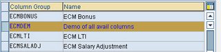
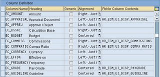
As you can see from the image above, you have Column Name, Heading, Alignment, and FM for Columns Contents. In the "FM for Column Contents" is where you specify the custom function module for the custom columns. SAP delivers a lot of standard column for ECM 5.0, you should look through them first to see if it exist prior to creating your own.
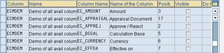
In the "Define Column Group", you have two pieces to configure. The first one is "Define Column Groups" (table: V_TWPC_ARRAYTP) and the second one is "Assign Columns To A Column Group" (table: V_TWPC_ACOL_C or V_TWPC_ACOL). In the "Define Column Groups" you will define the name where you will group all of these columns in earlier step together. In our example, we will call it as ECMDEM.


In the second section, "Assign Columns To A Column Group" is where you link all of the columns you've identify to the column group you gave the name to earlier (ECMDEM).


As you can see from the image above, ECMDEM column group has 6 columns (in actual table there are more, but screenshot has been cropped for blog). The position column shown above determine the position of the column from left to right. The "Visible" column forced the column to be visible and can not be hide from the USER profile in MSS. The next column you don't see is called "DO NOT DISPLAY", this will totally hide the column. The last column you need to know is "Invisible". Which allow the USER Profile in MSS to hide the column at the user level.

The last piece of config on the R/3 side is "View Definition" (table V_TWPC_V). I am not sure where this is located on the IMG step, I've always go to the table directly. This table specify what column group to use on the MSS portal side. The view name is what is used on the portal iview configuration.


The "View" field will be used on the portal content adminstration side. This is what you tell your portal administrator to reference the iview from. See sample portal content administration screen below.


Now you've completed a simple walkthru on how to quickly modify columns for MSS ECM 5.0 screen. Chances are you might have access to do the R/3 configuration, however you would need to work with the portal team on modifying the portal iview to specify the proper view name.

A couple of things you need to know and remember. First is some of these fields are considered as dynamic driven fields. Such as Compa Ratio, New Base Salary, etc. In order for these fields to properly work, a setting need to occur. Second is there are limitation to how many columns you could display. While you have more shown on the R/3 table configuration, there is a max of how many could be show on the portal screen. The MSS User would need to de-select which of those they don't care to show and select those they care to show. Please refer to main SAP HELP document (link provided top of blog) for further information. Otherwise, you will be scratching your head for days trying to figure out why there are no data showing in these fields.

Lastly, from what I've gathered, ECM in later version after 5.0 have slight changes to how the portal screen look like. As the result, this method might not be correct for later version. Please refer to their documents for further details.

Enterprise Services Documentation Download

On this page, you can find every document related to enterprise services. The documentation provided here explains everything from the transactions required to maintain enterprise services to the required information to consume enterprise services. In addition, the comprehensive documentation for each application type ranges from the business content and usage of enterprise services to detailed technical information.

The documents are grouped by the process components they belong to. That way, you should be able to find all semantically related documents in one place. All documents are in PDF format, so that you can save them and refer to them offline as often as you need.


Document Downloads

You can download the documentation packages from the links below:

ERP 2004 documentation (ZIP 4.6 MB)

ERP 2005 documentation (ZIP 10.6 MB)

SCM documentation (ZIP 4.4 MB)

SRM documentation (ZIP 2.4 MB)

CRM documentation (ZIP 2.2 MB)
All Rights Reserved